This is an excerpt from "How Magnetic Bearings Work" document. To read the preceding section click here.
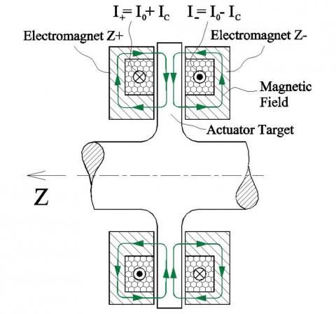
In addition to radial support, turbomachinery rotors normally require axial support as well. The structure of a conventional axial magnetic bearing used by most magnetic bearing companies is shown in Fig. 12. The operation of this bearing is identical to the operation of the radial bearing shown in Figs. 7 and 8.
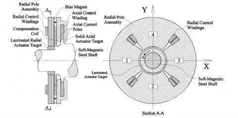
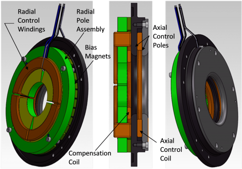
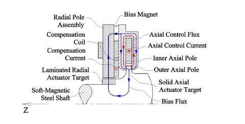
Depending on the situation, Calnetix sometimes also uses the axial bearing shown in Fig. 12 as well as a variety of PM-biased radial bearings. In most cases, however, Calnetix selects a patented unique magnetic bearing design that combines functions of both axial and radial bearing in one device - combo magnetic bearing. The structure of this bearing is shown in Fig. 13, 3D representation in Fig. 14 and the operational principle is explained in Fig. 15.
The structure of the combination bearing shown in Figs. 13 and 14 is largely similar to the structure of the radial bearing shown in Figs. 9-10 but the dead pole is replaced with two axial poles located on the axially opposite sides of a solid axial actuator target. The bias flux generated by the permanent magnet flows radially in the radial pole assembly exactly as it does in the radial bearing per Figs. 9-11, but on return it gets divided between two axial poles (see Fig. 15).
If the axial actuator target is centered between the inner and outer axial poles, the magnetic flux density on the left side of the target would be almost the same as on the right side and the net axial force on the target would be approximately zero. An axial control coil sandwiched between two axial poles induces magnetic axial control flux in those poles when energized with a current. This flux circulates in a loop formed by the axial control poles magnetically connected to each other on the OD and an axial actuator target. It does not propagate much into the radial pole assembly because it is difficult for it to cross the permanent magnet (the permanent magnet has a large magnetic reluctance).
When the axial control winding is energized with a current directed as shown in Fig. 15, it adds to the bias flux in the inner (left) axial pole and subtracts from it in the outer (right) axial pole, resulting in a higher magnetic flux density on the left side of the actuator axial target than on the right side, and, consequently, an axial force pulling the rotor to the left (positive Z direction). Reversing direction of the axial current reverses the direction of force.
The compensation coil sandwiched between the radial pole assembly and the inner axial pole serves to stabilize the bias magnetic flux when the axial control coil is energized with a current. The compensation coil and the axial control coil are connected in series but wound in the opposite directions.
Mechanism of generating radial forces in the combo bearing is exactly the same as in the radial bearing and can be understood from Fig.11 and the accompanying description.
FIG. 12
FIG. 13
FIG. 14
FIG. 15
Advantages of using a combination bearing per Figs. 13-15 instead of an arrangement of separate radial and axial bearings such as shown in Fig. 12 include:
Shorter axial length leading to a more compact design and better rotordynamics
Lower aerodynamic drag due to lower axial actuator target OD
Lower stresses in the rotor due to lower axial actuator target OD
Lower part count
Lower cost
In many cases, better axial bandwidth (more load capacity at higher frequencies)